DAQ Hardware
SlinkRocket
FIREFLY
The media used is FIREFLY (SAMTEC). The FIREFLY used has 4 fibres as transmitter and 4 fibres as receiver working up to 28Gb/s, per module. The same media is used when SlinkRocket works at 15.66 Gb/s, in this configuration, the internal CDR is switch OFF
Note
DTH_P2 all SlinkRocket links work @ 25.78125 Gb/s only.
To concentrate connections at the front panel, we decided to merge 2 FIREFLY's per MPO connector.
- You can find the MPO connectivity in this file (for DTH_P2). OTP-231227-XX-ECUO_25Gb
The front panel connection to the FIREFLY is done via a MPO adapter (KeyUP/KeyDown). To connect your SlinkRocket to the DTH you have multiple choices.
-
You have a MPO24 coming out of your card and the fibre positions are the same as our FIREFLY(see OTP-xxx.pdf file above).
- you can use such a cable https://www.fs.com/fr/products/30931.html type B.
Warning
With a type B fibe Module A will arrive to Module B and B to A.
-
You have a MPO12 coming out of your card and the fibre position is compatible with our FIREFLY.
FS.COM (or others) can provide custom MPO24 to 2x MPO12.
Warning
WPay attention on the position of TX and RX links.
-
You do not comply with the 2 above solutions, in this case is better to use a breakout MPO24 to LC fibre cable.
- you can use such a cable https://www.fs.com/fr/products/31191.html type B (in this case you have all the flexibility).
Don't hesitate to ask if you have a doubt on the connectivity. You can find also a fibre polarity explanation here.
Protocol and IP cores
SlinkRocket is the protocol used to transmit data form the FED ATCA card to the DTH_400 or DAQ_800 card. See below the data format. The protocol is used over an optical link working @ 25,78125 Gb/s.
Warning
Only the DTH_P1 supports the 15.66Gb/s
The protocol uses up to 4 blocks of 4Kbytes to transmit fragments on the fibre. Each block includes a CRC to validate it at the reception
Note
You can find document/code (USB CRC16 code or link(1) (2).
However this protocol is hidden from the user. The user interface of the SlinkRocket is conceptionally very similar to the previous generation of the SLINK protocol in DAQ CMS (only data width has changed).
The SlinkRocket cores (sender and receiver) are available in GitLab as an IP for Xilinx FPGA (only for Kintex and Virtex Ultrscale+). Be sure to use tagged versions and not the master branch. The Users manual for the IP cores can be downloaded from Gitlab.
The SlinkRocket sender side has registers which can be read from the receiver side. You can found documentation of this in the SlinkRocket repo
There exist two example designs implementing one or 4 Slink Rocket links with VCU118 development board of Xilinx. How to compile this design is described in the SlinkRocket Users Manual mentioned above.
Event fragment
Event Fragments send by sub-detectors have to fulfill a format. The word size is 128 bits. The format is composed by a Header, a payload (which can be empty) and a Trailer. The Header and Trailer formats are defined in: https://edms.cern.ch/document/2502737/
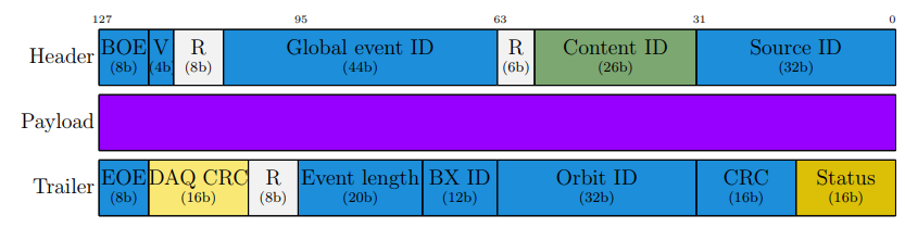
The data format of the SlinkRocket. The fields are described in detail in the EDMS note 2502737.
In the Header and the Trailer fields have meaning and should be fill as explained below:
- BOE.......................: 0x55 Begining Of Event
- V.............................: Header and Trailer format version (0x1)
- Global_Event_ID....: The level-1 event number generated by the TTC system.
- E............................: Emulator data source
- 00 when data from real FED
- 01 when data from the SlinkSender emulator
- 10 when data from the DAQ emulator
- Physic Type...........: Event type identifier (see table below)
- L1A type & content:
-
Source_ID.............: Unambiguously identify the data source (FED/DCC). The source_id field is currently defined in the source
-
EOE.......................: 0xAA End Of Event
- DAQ CRC..............: USB CRC16 calculated by the SlinkRocket Sender, which is compared with the CRC calculated by the Sub-D.
- Event_Length.........: number of 128b words (Header and Trailer are included) max: 16Mbytes
- BX_ID.....................: Bunch Crossing number. Reset on every LHC orbit
- Orbit_ID..................: Orbit number
- CRC.......................: USB CRC16 calculated by the Sub-Detector.
- CRC calculation includes the header and the trailer
- It excludes the CRC and Status fields which must be set to x"0000" during the calculation
- Status
- bit 0 : FED CRC error(s)
- bit 1 : Slink CRC error(s)
- bit 2 : Source_ID error
- bit 3 : SynLost
- bit 4 : Fragment Cut (TOO LONG)
- others : reserved for future definition
The following table is a preliminary definition ot Event Types
| Type | Name | Comment |
|---|---|---|
| 001 | Physics trigger | Final OR (physics algorithms) |
| 002 | Calibration trigger | Calibration cycle |
| 003 | Test trigger | Test cycle |
| 004 | Technial trigger | Technical trigger (external trigger) |
| 005 | Simulated events | Reserved for DAQ usage |
| 006 | Traced events | Reserved for DAQ usage |
| 007 | Error | others unidefined |
DAQ 100Gb
Orbit Organization
You can see the document explaining how fragments are organized by the DTH : cms-phase2-orbitAggregation.pdf