User's guide
This guide describes the most important features of the DTH-400 ATCA card and it’s RTM card.
DTH_400
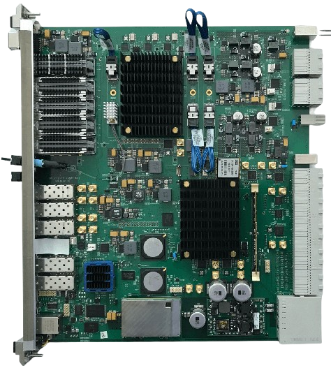
Three functionalities are implemented on this board:
- DAQUnit (upper FPGA): implements DAQ functionality with up to 24 SLINK rockets and up to 5 100Gbps TCP/IP output links.
- TCDS-2 interfaces: Interfaces to the TCDS-2 Captain and provides TCDS-2 clock and data stream via the backplane to sub-system blades.
- Network switch: Provides network connectivity for all blades in the shelf via a network switch with up to two 10Gbps uplinks.
Info
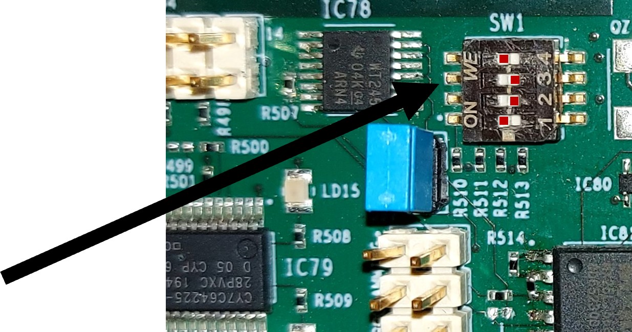
If you want to use a second DTH_400 in HUB2 slot, for the moment, you should disable the Ethernet switch of the DTH_400 in HUB2 and connect the RTM to the network via the RTM front panel (see RTM J11 below). To disable the DTH_400 ethernet switch, set the switch SW1 to the value (ON-OFF-OFF-ON) (see picture). (normal setup is OFF-OFF-OFF-OFF)
DTH_400 as a NODE or in the second HUB slot
Hardware setup and modifications
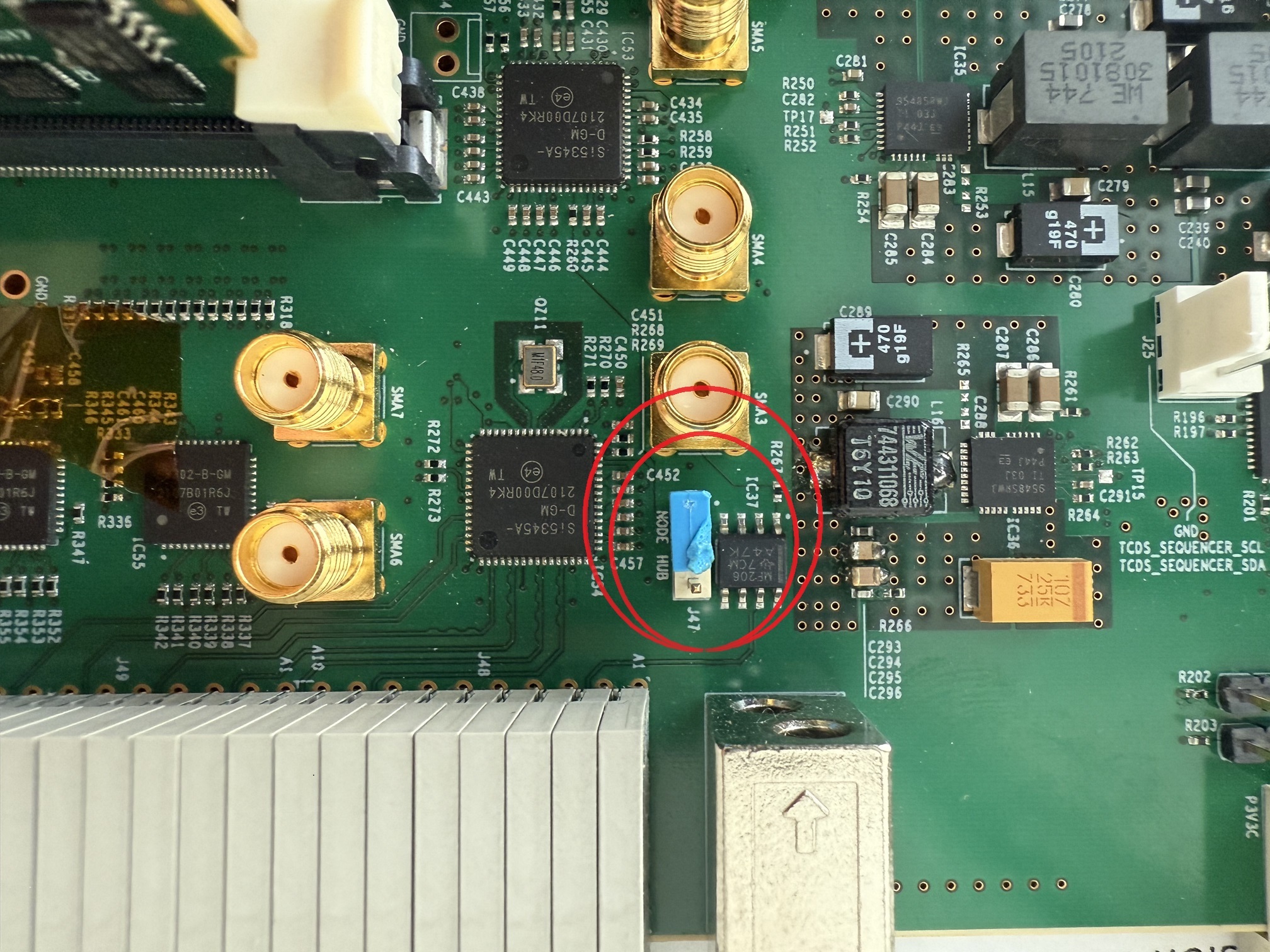
In case you want to use the DTH_400 in a NODE slot or in the second HUB slot, some modifications have to be done. The DTH_400 (as a node) can only use the TCDS2 from the HUB1.
You must change the corresponding J47 jumper (only if the card is in a NODE slot), as shown in the below image:
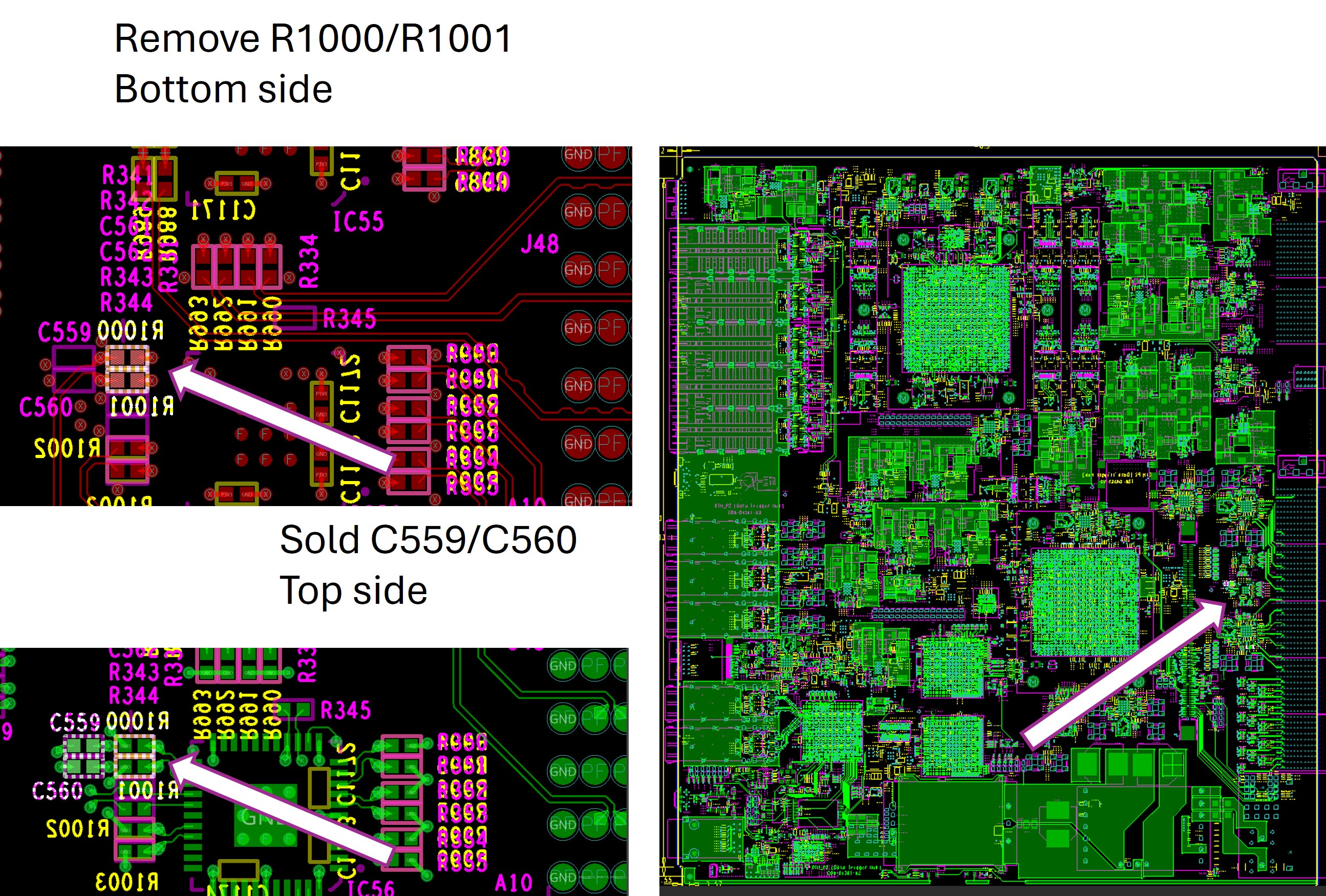
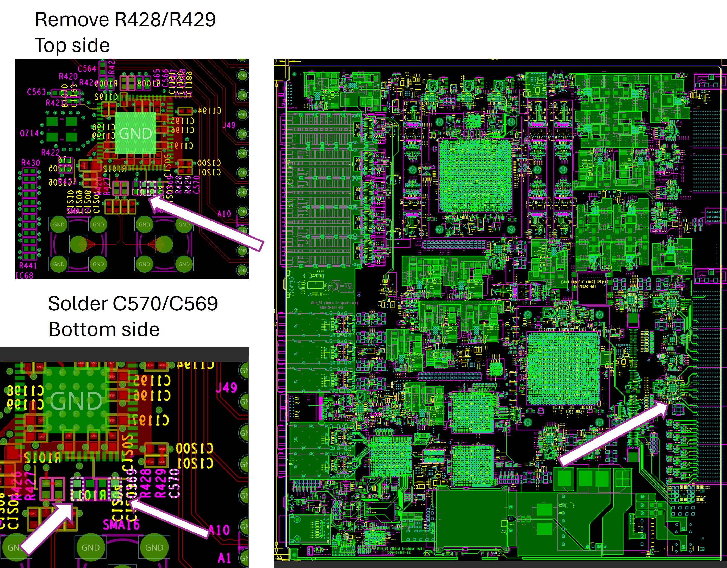
A second modification has to be done to avoid any damage on the card. Two TCDS clock paths have to be modified. (Do not hesitate to ask us to do the modifications for you)
Warning
Four resistors (R1000-R1001-R428-R429) must be removed and four capacities (C569-C570-C559-C560) must be soldered. IN ADDITION, if a DTH_400 is installed in the second HUB slot (working as a node or as a HUB), R1002-R1003 should be removed. And a special file should be used to configure IC57. (ASK DAQ expert if you are in this case).
Info
If the card installed in the second HUB slot, the capacities (C569-C570-C559-C560) should be mounted and resistors (R1000-R1001-R428-R429) should be removed if the DTH is part of the same TCDS2 "partition" of the DTH in the first HUB slot.
If you want to use the modified DTH in the first HUB slot, you can do so (without risking any damage) but the clock delivered to the second HUB slot will not be delivered if you do not reverse the modifications applied before.
TCDS FPGA firmware
When DTH is in NODE slot, the TCDS fpga should be configured with a special firmware to forward the TCDS2 from/to the backplane to/form the DAQ fpga. Use the firmware : DTH_p2_TCDS_forward_df100002.bin
The TCDS clock system of the TCDS FPGA has to be reconfigured with the following command :
    sudo podman run -it --privileged --rm --network=host \
    --name dthdaqtools --pull=newer \
    --replace gitlab-registry.cern.ch/dth-daq-unit/dth-daq-tools/dth-daq-tools-alma9-aarch64:<dth_daq_tools_version> \
    program_clocks_i2c DTH_tcds
dth_daq_tools_version
The "dth_daq_tools" version can be find here
When done the TCDS FPGA should be reloaded using the folowing command
DAQ FPGA firmware
The Firmware for the DAQ fpga is the same when the DTH is used in HUB or NODE slot.
DTH_400 Front Panel
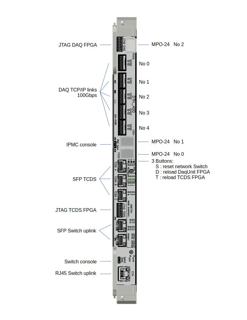
Next to the debugging JTAG connector on the top, you find a MPO-24 connector for 8 Slink connection .the 5 QSFP slots for the DAQ 100Gbps TCP/IP links.
On the bottom end of the front panel you see one RJ45 and 2 SFP optical connectors. One of these can be use as an uplink of the internal network switch (i.e. one of these can be connected to the “outside network”). However, be sure to only connect one of these three network connector since otherwise you create a network loop which will bring down the entire laboratory network (or more…)!
Under the MPO-24 connector No 0, you find three buttons which allow to force the reload of the FPGA firmware (one button for each FPGA) or to reset the network switch.
RTM card
IMPORTANT NOTE: Please do not insert other jumpers and do not change the settings of the dip switches on the board. You could generate a short between powerlines together with a one-time fireworks on your card, or you will make the card unusable (e.g. it does not boot anymore).
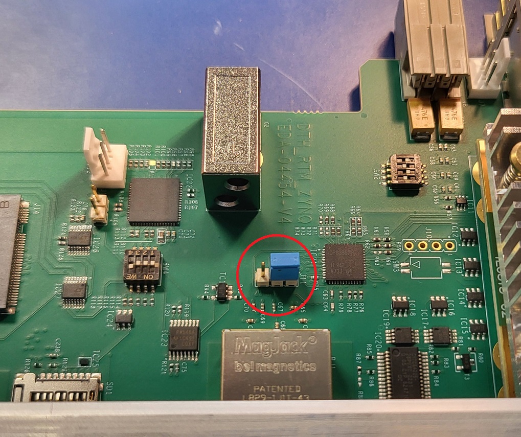
You may only change the settings of J11 (see below) in case this is useful for you (normally this is not recommended or needed).
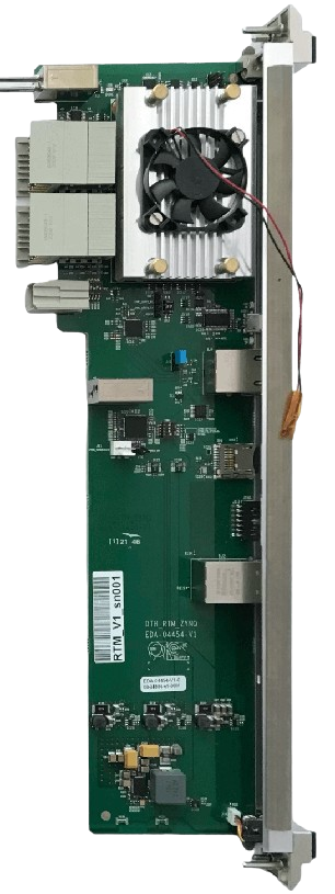
The RTM card houses the Zynq based system controller. A Kria controller is used for this embedded computer. In CMS it runs Alma Linux on top of a Petalinux kernel from Xilinx.
The lowest level bootloader code for the RTM card is contained in a on-board flash. This code reads a second stage bootloaded (U-BOOT) from the SD card which needs to be plugged into the foresee slot on the front-panel of the RTM card. This bootloader then initiates a network boot procedure.
In principle it is also possible to boot from the SD card or from a NVMe SSD memory module on board of the RTM. However, this is currently not supported by the DAQ group.
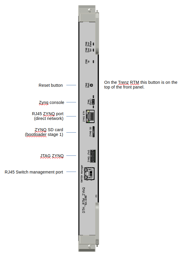
Front Panel of the RTM
On the top a reset button can be used to hard-reset the controller.
A micro-usb port allows to connect a console to a computer. Once plugged into a linux computer a device /dev/ttyACM0 appears and can be attached to the minicom utility:
minicom -D /dev/ttyACM0
The console is then connected to the computer and can be used for debugging. Settings for the terminal are standard (in general the default settings of minicom are correct) : 115200 baud, 8NP.
Alternatively you can access the ZYNQ console through the IPMC (for this, no cable should be plugged on the micro-usb connector).
ipmitool -C 3 -I lanplus -H atca-lab40-r01-02p-ipmc.cern.ch -U "" -P "" -k gkey sol payload enable
ipmitool -C 3 -I lanplus -H atca-lab40-r01-02p-ipmc.cern.ch -U "" -P "" -k gkey sol activate
atca-lab40-r01-02p in this example is the name used for the IPMC clientID
The RTM front panel houses two RJ45 connectors. The upper connector provides direct network connectivity to the Kria. To use this connector the jumper J11 needs to be set to the upper position. To connect the KRIA to the switch on the DTH-400, the jumper should be in the lower position. The photo below shows the location of the Jumper on the RTM on the board. (In addition the photo shows the correct settings of the DIP switches which you should cross check before operating the board).
The lowerRJ45 connector provides a connection to the management port of the network switch on the DTH-400. It is not needed for normal operation or setup.
IPMC
Further Documentation
Within this website link to a table with the preseries boards (containing the MAC addresses of all boards): Click on “Cards” and follow the link “Table” on that page:
https://cernbox.cern.ch/s/4geP9YUhFgkJfqO
Gitlab pages with instructions to install the network services to boot and run the system controller.
https://gitlab.cern.ch/hardware/phase2/network-services
Instructions to run the DAQ Unit controller:
https://cms-dth-daq.docs.cern.ch/
Instructions to install and run the TCDS-2 utilities on the System controller: